Hokheng Hou
2017-10-28 12:50
Static Route to Provide Network Connectivity between each PC
2928 Views
2017-10-28 12:50
ចង់ប្តូរការងារ ឬ កំពុងស្វែងរកការងារ ផ្វើសារឥឡូវនេះ
This lab is focusing on basic Static Route, Vlan, Telnet, used to connect all network together in order to provide network connectivity between each PC (refer to the network topology), telnet to relevant equipment.
Material:
1.Two 1841 Cisco Routers
2.Four 2950-24 Cisco Switch
3.Four PC
Requirement:
1.All PC can ping each other
2.PC1 and PC3 can Telnet R1 and R2
3.All Switch (Sw-1, Sw-2, Sw-3 and Sw-4) can Telnet R1 and R2
4.Sw-1 can ping Sw-2 and Sw-3 can ping Sw-4
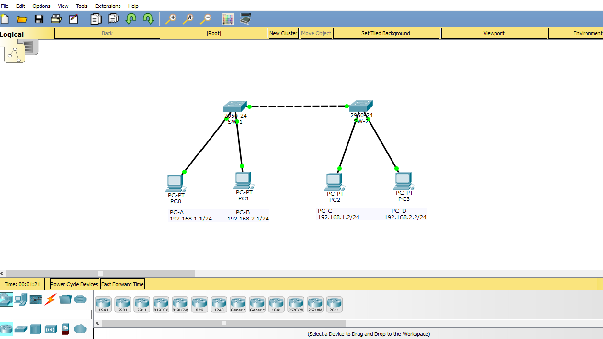
Network Topology:
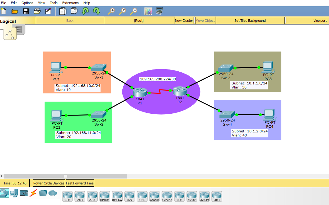
Configuration Guide:
1.All PC can ping each other
###Assign all IP Address on all PC###
***PC1:
IP Address: 192.168.10.2
Mask: 255.255.255.0 (/24)
Gateway: 192.168.10.1
Vlan: 10 (name: Admin-1)
***PC2:
IP Address: 192.168.11.2
Mask: 255.255.255.0 (/24)
Gateway: 192.168.11.1
Vlan: 20 (name: use default name)
***PC3:
IP Address: 10.1.1.2
Mask: 255.255.255.0 (/24)
Gateway: 10.1.1.1
Vlan: 30 (name: Admin-2)
***PC4:
IP Address: 10.1.2.2
Mask: 255.255.255.0 (/24)
Gateway: 10.1.2.1
Vlan: 40 (name: use default name)
###Configuration on each Switch###
***Sw-1:
Sw-1(config)#vlan 10
Sw-1(config-vlan)#name Admin-1
Sw-1(config)#interface fastEthernet 0/2
Sw-1(config-if)#description ***Sw-1 to PC1***
Sw-1(config-if)#switchport mode access
Sw-1(config-if)#switchport access vlan 10
Sw-1(config-if)#no shutdown
Sw-1(config)#interface fastEthernet 0/1
Sw-1(config-if)#description ****Sw-1 to R1***
Sw-1(config-if)#switchport mode access
Sw-1(config-if)#switchport access vlan 10
Sw-1(config-if)#no shutdown
***Sw-2:
Sw-2(config)#vlan 20
Sw-2(config)#interface fastEthernet 0/2
Sw-2(config-if)#description ***Sw-2 to PC2***
Sw-2(config-if)#switchport mode access
Sw-2(config-if)#switchport access vlan 20
Sw-2(config-if)#no shutdown
Sw-2(config)#interface fastEthernet 0/1
Sw-2(config-if)#description ****Sw-2 to R1***
Sw-2(config-if)#switchport mode access
Sw-2(config-if)#switchport access vlan 20
Sw-2(config-if)#no shutdown
***Sw-3:
Sw-3(config)#vlan 30
Sw-3(config-vlan)#name Admin-2
Sw-3(config)#interface fastEthernet 0/2
Sw-3(config-if)#description ***Sw-3 to PC3***
Sw-3(config-if)#switchport mode access
Sw-3(config-if)#switchport access vlan 30
Sw-3(config-if)#no shutdown
Sw-3(config)#interface fastEthernet 0/1
Sw-3(config-if)#description ****Sw-3 to R2***
Sw-3(config-if)#switchport mode access
Sw-3(config-if)#switchport access vlan 30
Sw-3(config-if)#no shutdown
***Sw-4:
Sw-4(config)#vlan 40
Sw-4(config)#interface fastEthernet 0/2
Sw-4(config-if)#description ***Sw-4 to PC4***
Sw-4(config-if)#switchport mode access
Sw-4(config-if)#switchport access vlan 40
Sw-4(config-if)#no shutdown
Sw-4(config)#interface fastEthernet 0/1
Sw-4(config-if)#description ****Sw-4 to R2***
Sw-4(config-if)#switchport mode access
Sw-4(config-if)#switchport access vlan 40
Sw-4(config-if)#no shutdown
After finish these part, all PC can ping its own gateway, but still not yet able to ping each other. Checking ping testing below:
Both of PC1 & PC3 can ping its own gateway, But cannot ping each other.
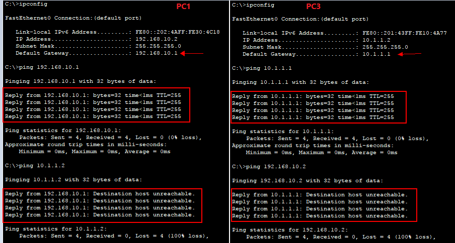
To make connection between each PC, we need to do routing by using Static Route in this lab as below:
***For R1:
R1(config)#ip route 10.1.1.0 255.255.255.0 209.165.200.226
R1(config)#ip route 10.1.2.0 255.255.255.0 209.165.200.226
or
R1(config)#ip route 10.1.1.0 255.255.255.0 serial 0/1/0
R1(config)#ip route 10.1.2.0 255.255.255.0 serial 0/1/0
***For R2:
R2(config)#ip route 192.168.10.0 255.255.255.0 209.165.200.225
R2(config)#ip route 192.168.11.0 255.255.255.0 209.165.200.225
or
R2(config)#ip route 192.168.10.0 255.255.255.0 serial 0/1/0
R2(config)#ip route 192.168.11.0 255.255.255.0 serial 0/1/0
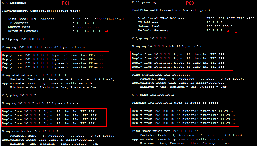
After finish routing above, we check the result again:
2.PC1 and PC3 can Telnet R1 and R2
***R1:
R1(config)#enable password cisco
R1(config)#line vty 0 4
R1(config-line)#password 123
R1(config-line)#transport input all
R1(config-line)#access-class 10 in
R1(config)#access-list 10 permit host 192.168.10.2
R1(config)#access-list 10 permit host 10.1.1.2
R1(config)#access-list 10 deny any (optional)
***R2:
R2(config)#enable password cisco
R2(config)#line vty 0 4
R2(config-line)#password 123
R2(config-line)#transport input all
R2(config-line)#access-class 10 in
R2(config-line)#access-list 10 permit host 192.168.10.2
R2(config)#access-list 10 permit host 10.1.1.2
R2(config)#access-list 10 deny any
Testing Result:
***PC1
C:\>telnet 192.168.10.1
Trying 192.168.10.1 ...Open
User Access Verification
Password:
***PC3
C:\>telnet 192.168.10.1
Trying 192.168.10.1 ...Open
User Access Verification
Password:
***PC2
C:\>telnet 192.168.11.1
Trying 192.168.11.1 ...
% Connection refused by remote host
***PC4
C:\>telnet 192.168.11.1
Trying 192.168.11.1 ...
% Connection refused by remote host
3.Sw-1 can ping Sw-2 and Sw-3 can ping Sw-4
To make connectivity between each switch, we need to assign ip address and vlan on switch as below:
Sw-1(config)#int vlan 10
Sw-1(config-if)#ip address 192.168.10.254 255.255.255.0
Sw-1(config)#ip default-gateway 192.168.10.1
Sw-2(config)#int vlan 20
Sw-2(config-if)#ip address 192.168.11.254 255.255.255.0
Sw-2(config)#ip default-gateway 192.168.10.1
Sw-3(config)#int vlan 30
Sw-3(config-if)#ip address 10.1.1.254 255.255.255.0
Sw-3(config)#ip default-gateway 10.1.1.1
Sw-4(config)#int vlan 40
Sw-4(config-if)#ip address 10.1.2.254 255.255.255.0
Sw-4(config)#ip default-gateway 10.1.1.1
****Testing Result:
Sw-1 ping Sw-2
Sw-1>ping 192.168.11.254
Type escape sequence to abort.
Sending 5, 100-byte ICMP Echos to 192.168.11.254, timeout is 2 seconds:
!!!!!
Success rate is 100 percent (5/5), round-trip min/avg/max = 0/0/0 ms
Sw-3 ping Sw-4
Sw-3>ping 10.1.2.254
Type escape sequence to abort.
Sending 5, 100-byte ICMP Echos to 10.1.2.254, timeout is 2 seconds:
!!!!!
Success rate is 100 percent (5/5), round-trip min/avg/max = 0/0/1 ms
4.All Switch (Sw-1, Sw-2, Sw-3 and Sw-4) can Telnet R1 and R2
We need to allow access on the acl as below:
R1:
R1(config)#access-list 10 permit host 192.168.10.254
R1(config)#access-list 10 permit host 192.168.11.254
R1(config)#access-list 10 permit host 10.1.1.254
R1(config)#access-list 10 permit host 10.1.2.254
R2
R2(config)#access-list 10 permit host 192.168.10.254
R2(config)#access-list 10 permit host 192.168.11.254
R2(config)#access-list 10 permit host 10.1.1.254
R2(config)#access-list 10 permit host 10.1.2.254
Testing (ex. Sw-1):
Sw-1 telnet to R1
Sw-1#telnet 192.168.10.1
Trying 192.168.10.1 ...Open
User Access Verification
Password:
Sw-1 telnet to R2
Sw-1#telnet 10.1.1.1
Trying 10.1.1.1 ...Open
User Access Verification
Password:
***Note:
Enable password: cisco
Line vty password: 123
Full Lab Click on download
អត្ថបទណែនាំ
ធ្វើការត្រូវការបទពិសោធន៍ ប៉ុន្តែមិនទាន់ធ្វើការផងធ្វើម៉េចមានបទពិសោធន៍!
ដោយ : ភក្តី Talk 9 days ago

ហេតុអ្វីបានជាយើងត្រូវបំបែកពេលវេលាផ្ទាល់ខ្លួននិងការងារ។? Why we need to "Separate" Work and Life
ដោយ : ភក្តី Talk 14 days ago

តើគួរទិញកុំព្យូរទ័របែបណា? ទិញ Laptop ឬ Desktop?
ដោយ : ភក្តី Talk 24 days ago

AI chatbot development services
ដោយ : fringe963@gmail.com 1 month ago
សំណួរត្រៀមប្រឡង_ឆមាស២ Kompong Speu high school 2026
ដោយ : Davidfriendly 2 months ago
ខ្លាចជ្រើសរើសជំនាញខុស? មិនដឹងថាខ្លួនឯងត្រូវរៀនជំនាញណាស់ឲ្យប្រាកដ?
ដោយ : ភក្តី Talk 2 months ago

ដោយ : fringe963@gmail.com 2 months ago
អត្តបទបន្ថែមទៀត
Question and Answer and Blog, Why Using KhSearch.com?
ដោយ : KhSearch 8 years ago
បញ្ចុះតម្លៃ 50%ពី Café’ Chapayom នៅក្នុងបុណ្យហាឡូវីន
ដោយ : KhSearch 8 years ago

ដោយ : KhSearch 8 years ago

អាហារូបករណ៍ថ្នាកបណ្ឌិតនៅប្រទេសសិង្ហបុរី
ដោយ : KhSearch 8 years ago


ដោយ : Novel Collection 8 years ago

ដោយ : Novel Collection 8 years ago

Connection between each PC within the same vlan but different switches
ដោយ : Hokheng Hou 8 years ago
2BR Cleaned Apartment For Rent In Wat Phnom $600/month
ដោយ : Property 8 years ago

Brand new & Bright, Nice Furnished $450/Month
ដោយ : Property 8 years ago

អត្ថបទថ្មីៗទាក់ទងបទពិសោធន៍ផ្សេងៗ
ម៉ាស៊ីនបោះពុម្ព Print អត់ចេញក្រដាស - Can’t print: Troubleshooting steps
ដោយ : Pich Yorn 3 months ago
របៀបសំអាត file មិនសំខាន់ៗនៅក្នុង computer - Clean computer temp
ដោយ : Pich Yorn 3 months ago
IT-Support ,Network Computer Management
ដោយ : ស៊ីថា ទិត្យ 4 months ago
Network , Switch , Router , Wifi Configuration ... Backup Share ,Task of network system