Chenda SOK
2019-12-13 13:52
Configuring a Layer 3 Switch to Work with a Router for Internet Access
2386 Views
2019-12-13 13:52
ចង់ប្តូរការងារ ឬ កំពុងស្វែងរកការងារ ផ្វើសារឥឡូវនេះ
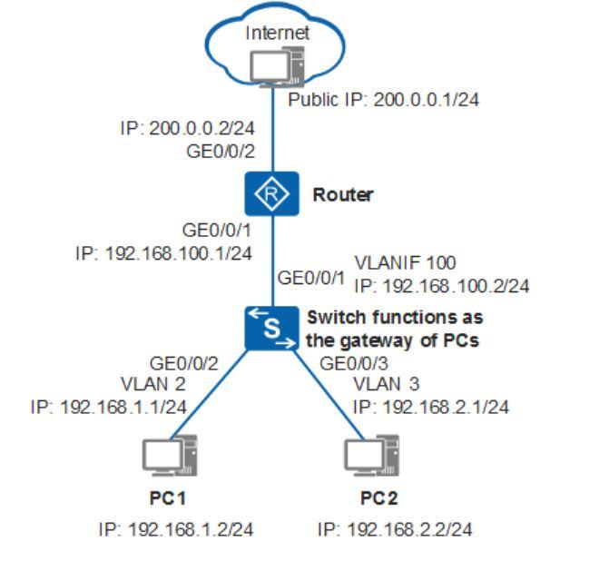
Configuration Roadmap
The configuration roadmap is as follows:
Configure the switch as the gateway of users to allow users to communicate across network segments through VLANIF interfaces.
Configure the switch as the DHCP server to assign IP addresses to users.
Configure the NAT function on the router to enable intranet users to access the Internet.
Procedure
# Configure the interfaces connected to users and corresponding VLANIF interfaces.
<Quidway> system-view
[Quidway] sysname Switch
[Switch] vlan batch 2 3
[Switch] interface gigabitethernet 0/0/2
[Switch-GigabitEthernet0/0/2] port link-type access //Set the link type of the interface to access.
[Switch-GigabitEthernet0/0/2] port default vlan 2 //Add the interface to VLAN 2.
[Switch-GigabitEthernet0/0/2] quit [Switch] interface gigabitethernet 0/0/3
[Switch-GigabitEthernet0/0/3] port link-type access
[Switch-GigabitEthernet0/0/3] port default vlan 3
[Switch-GigabitEthernet0/0/3] quit
[Switch] interface vlanif 2
[Switch-Vlanif2] ip address 192.168.1.1 24
[Switch-Vlanif2] quit [Switch] interface vlanif 3
[Switch-Vlanif3] ip address 192.168.2.1 24
[Switch-Vlanif3] quit
# Configure the interface connected to the router and corresponding VLANIF interface.
[Switch] vlan batch 100
[Switch] interface gigabitethernet 0/0/1
[Switch-GigabitEthernet0/0/1] port link-type access
[Switch-GigabitEthernet0/0/1] port default vlan 100
[Switch-GigabitEthernet0/0/1] quit
[Switch] interface vlanif 100
[Switch-Vlanif100] ip address 192.168.100.2 24
[Switch-Vlanif100] quit
# Configure the default route.
[Switch] ip route-static 0.0.0.0 0.0.0.0 192.168.100.1
# Configure the DHCP server.
[Switch] dhcp enable
[Switch] interface vlanif 2
[Switch-Vlanif2] dhcp select interface
[Switch-Vlanif2] dhcp server dns-list 114.114.114.114 223.5.5.5
[Switch-Vlanif2] quit
[Switch] interface vlanif 3
[Switch-Vlanif3] dhcp select interface
[Switch-Vlanif3] dhcp server dns-list 114.114.114.114 223.5.5.5
[Switch-Vlanif3] quit
2. Configure the router.
# Configure an IP address for the interface connected to the switch.
<Huawei> system-view
[Huawei] sysname Router
[Router] interface gigabitethernet 0/0/1
[Router-GigabitEthernet0/0/1] ip address 192.168.100.1 255.255.255.0
[Router-GigabitEthernet0/0/1] quit
# Configure an IP address for the interface connected to the Internet.
[Router] interface gigabitethernet 0/0/2
[Router-GigabitEthernet0/0/2] ip address 200.0.0.2 255.255.255.0
[Router-GigabitEthernet0/0/2] quit
# Configure a default route and a return route.
[Router] ip route-static 0.0.0.0 0.0.0.0 200.0.0.1
[Router] ip route-static 192.168.0.0 255.255.0.0 192.168.100.2
# Configure the NAT function to enable intranet users to access the Internet.
[Router] acl number 2001
[Router-acl-basic-2001] rule 5 permit source 192.168.0.0 0.0.255.255
[Router-acl-basic-2001] quit
[Router] interface gigabitethernet 0/0/2
[Router-GigabitEthernet0/0/2] nat outbound 2001
[Router-GigabitEthernet0/0/2] quit
3. Check the configuration.
Configure an IP address 192.168.1.2/24 and a gateway address 192.168.1.1 for PC1, and configure an IP address 192.168.2.2/24 and a gateway address 192.168.2.1 for PC2.
Configure an IP address 200.0.0.1/24 and a gateway address 200.0.0.2 for external network.
After the configurations are complete, PC1 and PC2 can ping the external network IP address 200.0.0.1/24 and access the Internet.
Configuration Files
#
sysname Switch
#
vlan batch 2 to 3 100
#
dhcp enable
#
interface Vlanif2
ip address 192.168.1.1 255.255.255.0
dhcp select interface
dhcp server dns-list 114.114.114.114 223.5.5.5
#
interface Vlanif3
ip address 192.168.2.1 255.255.255.0
dhcp select interface
dhcp server dns-list 114.114.114.114 223.5.5.5
#
interface Vlanif100
ip address 192.168.100.2 255.255.255.0
#
interface GigabitEthernet0/0/1
port link-type access port default vlan 100
#
interface GigabitEthernet0/0/2
port link-type access port default vlan 2
#
interface GigabitEthernet0/0/3
port link-type access port default vlan 3
#
ip route-static 0.0.0.0 0.0.0.0 192.168.100.1
#
return
#
sysname Router
#
acl number 2001
rule 5 permit source 192.168.0.0 0.0.255.255
#
interface GigabitEthernet0/0/1
ip address 192.168.100.1 255.255.255.0
#
interface GigabitEthernet0/0/2
ip address 200.0.0.2 255.255.255.0
nat outbound 2001
#
ip route-static 0.0.0.0 0.0.0.0 200.0.0.1
ip route-static 192.168.0.0 255.255.0.0 192.168.100.2
#
return
Reference:
https://support.huawei.com/enterprise/de/doc/EDOC1000069608/b18e74dc/example-for-configuring-a-layer-3-switch-to-work-with-a-router-for-internet-access
អត្ថបទណែនាំ
ធ្វើការត្រូវការបទពិសោធន៍ ប៉ុន្តែមិនទាន់ធ្វើការផងធ្វើម៉េចមានបទពិសោធន៍!
ដោយ : ភក្តី Talk 7 days ago

ហេតុអ្វីបានជាយើងត្រូវបំបែកពេលវេលាផ្ទាល់ខ្លួននិងការងារ។? Why we need to "Separate" Work and Life
ដោយ : ភក្តី Talk 12 days ago

តើគួរទិញកុំព្យូរទ័របែបណា? ទិញ Laptop ឬ Desktop?
ដោយ : ភក្តី Talk 22 days ago

AI chatbot development services
ដោយ : fringe963@gmail.com 1 month ago
សំណួរត្រៀមប្រឡង_ឆមាស២ Kompong Speu high school 2026
ដោយ : Davidfriendly 1 month ago
ខ្លាចជ្រើសរើសជំនាញខុស? មិនដឹងថាខ្លួនឯងត្រូវរៀនជំនាញណាស់ឲ្យប្រាកដ?
ដោយ : ភក្តី Talk 2 months ago

ដោយ : fringe963@gmail.com 2 months ago
អត្ថបទថ្មីៗទាក់ទងបទពិសោធន៍ផ្សេងៗ
ម៉ាស៊ីនបោះពុម្ព Print អត់ចេញក្រដាស - Can’t print: Troubleshooting steps
ដោយ : Pich Yorn 2 months ago

របៀបសំអាត file មិនសំខាន់ៗនៅក្នុង computer - Clean computer temp
ដោយ : Pich Yorn 3 months ago
IT-Support ,Network Computer Management
ដោយ : ស៊ីថា ទិត្យ 4 months ago
Network , Switch , Router , Wifi Configuration ... Backup Share ,Task of network system